Solutions to Mechanical Noise and Vibration: If the pump shaft and the motor shaft are misaligned, readjust the installation positions of the pump and the motor to meet the coaxiality requirements. If the bearing is damaged, replace the bearing in a timely manner.
-
For unreasonable pipeline design: Re - optimize the pipeline layout, reducing elbows and unnecessary throttling.
-
If air is mixed in the oil: Check whether the oil suction pipeline is well - sealed, eliminate the ways for air to enter the system, and at the same time, install an exhaust device in the system and vent it regularly.
Oil leakage not only causes waste of hydraulic oil and pollutes the working environment, but also affects the normal operation of the hydraulic system and may even trigger safety accidents. The main reasons for oil leakage failure are as follows:
-
Aging of seals: Seals are key components to prevent hydraulic oil leakage. With the increase of service time, seals gradually age, harden and lose their elasticity, resulting in a decline in sealing performance and oil leakage. Generally, the service life of seals is about 1 - 3 years, depending on the working environment and usage conditions.
-
Loosening of oil pipes: Under the long - term action of vibration and pressure, the joints of oil pipes may become loose, leading to seal failure and oil leakage. Improper installation position of oil pipes, being impacted or squeezed by external forces, can also cause the oil pipes to break and result in oil leakage.
-
Damage to the pump body: During the long - term operation of the oil pump, due to factors such as wear of internal parts and cavitation, cracks or pores may occur in the pump body, causing hydraulic oil to leak from these parts.
If the seals are aged, replace them with new ones. If the oil pipes are loose, tighten the pipe joints. If the pump body is damaged, repair or replace the pump body according to the degree of damage.
IV. Fault Diagnosis Methods
The visual inspection method is a way to preliminarily inspect the hydraulic press pumping station by using human senses such as sight, hearing, touch and smell to judge faults. This method is simple and easy to implement, does not require complex detection equipment, and can quickly detect some obvious fault signs.
During daily inspections, technicians can first carefully observe each component of the hydraulic press pumping station by sight. Check the state of the oil, including the cleanliness of the oil, whether there are bubbles, whether the oil quantity is sufficient, and whether the viscosity is normal. About 80% of hydraulic system failures are related to oil contamination. Therefore, observing the condition of the oil is of great significance for fault judgment. Also, pay attention to whether there are abnormal changes in the movement speed of the actuator, whether the pressure fluctuations at each pressure measurement point are normal, and whether there is oil leakage at parts such as the end cover of the hydraulic cylinder, the shaft end of the hydraulic pump, the joints of the hydraulic pipeline, and the joint surface of the oil circuit block and other control components. Observe whether the piston rod of the hydraulic cylinder has a jumping phenomenon, which may be caused by the presence of air in the hydraulic system or other faults. At the same time, pay attention to the quality of the products processed by the host, such as the surface roughness of the workpiece cut by the water jet. Changes in product quality may also reflect faults in the hydraulic press pumping station. In addition, checking materials such as system schematic diagrams, component lists, operation manuals, fault analysis and repair records helps to understand the normal operating parameters of the equipment and past fault conditions, providing a reference for fault diagnosis.
Hearing is also one of the important means of the visual inspection method. Technicians can judge the working state of the hydraulic press pumping station by listening to the noise. Listen to whether the noise of the hydraulic pump is too loud, whether the relief valve and sequence valve have a screeching sound. These abnormal sounds may indicate that the corresponding components have faults. Listen to whether the piston hits the bottom of the cylinder when the hydraulic cylinder changes direction, whether the directional valve hits the end cover when changing direction, and whether the pump has abnormal sounds such as air suction or oil entrapment. The occurrence of these sounds often means that there are problems in the hydraulic system and further inspection and repair are needed.
Touch can also help technicians discover some potential faults. Touch the outer surfaces of the pump, oil tank and valve. If it feels hot after touching for 2 seconds, it indicates that the temperature is too high and the cause of the high temperature needs to be checked. It may be due to system overload, poor heat dissipation or other faults. Touch whether the moving parts and pipes have high - frequency vibrations, which may be caused by loose mechanical parts, imbalance or pressure fluctuations in the hydraulic system. At low load and low speed, touch whether the worktable has a crawling phenomenon. The crawling phenomenon may be caused by factors such as the presence of air in the hydraulic system, oil contamination or uneven frictional resistance. In addition, use your hand to twist the stop iron, micro - switch, fastening screws, etc. to check whether they are loose. Loose parts may cause unstable operation of the equipment or faults.
Smelling can help detect whether the oil has a bad smell, which may be caused by oil oxidation, contamination or overheating. At the same time, pay attention to whether there is a smell of rubber due to overheating, which may indicate that some rubber seals or other rubber products are damaged in a high - temperature environment.
The instrument detection method is a method of accurately measuring the operating parameters of the hydraulic press pumping station using professional detection instruments such as pressure sensors, flow meters, and oil temperature detectors to judge faults. This method can provide accurate data support and help diagnose faults more accurately.
The pressure sensor is an important instrument for detecting the pressure of the hydraulic system. It can monitor the pressure at various parts of the system in real - time and convert the pressure signal into an electrical signal for output. By comparing with the normal operating pressure range of the system, abnormal pressure conditions can be detected in a timely manner. When the pressure sensor detects insufficient or excessive pressure, technicians can further investigate the cause of the fault according to the specific situation, such as checking whether the relief valve is working normally and whether the oil pump has a fault. The accuracy and reliability of the pressure sensor are crucial for fault diagnosis. Therefore, when selecting and using a pressure sensor, it is necessary to ensure that it meets the requirements of the system and calibrate and maintain it regularly.
The flow meter is used to measure the flow rate of hydraulic oil. By measuring the flow rate at different parts of the system, it can be judged whether there are problems of insufficient flow or unstable flow. If the flow meter detects insufficient flow, it may be due to reasons such as poor oil suction, oil pump wear or leakage. Unstable flow may be related to factors such as improper adjustment of the relief valve and variable mechanism failure. Through the analysis of flow data, technicians can carry out targeted fault investigation and repair.
The oil temperature detector can monitor the temperature of the hydraulic oil in real - time. Excessive oil temperature is one of the common faults of the hydraulic press pumping station. The oil temperature detector can timely detect the abnormal increase of oil temperature. When the oil temperature exceeds the normal range, technicians can check whether the oil is contaminated, whether the heat dissipation is poor or whether the system is overloaded, and take corresponding measures to solve them, such as replacing the hydraulic oil, cleaning the radiator or adjusting the system load.
In addition, other instruments can also be used, such as an oil contamination detector, which is used to detect the impurity content and particle size in the hydraulic oil to judge whether the oil is seriously contaminated; a vibration detector, which is used to detect the vibration of mechanical parts to judge whether there are mechanical faults, such as bearing damage and misalignment of the pump shaft and motor shaft. The comprehensive use of these instruments can more comprehensively and accurately diagnose the faults of the hydraulic press pumping station.
The experience - based analysis method is a way to infer and diagnose the faults of the hydraulic press pumping station based on the past maintenance experience of technicians and the accumulated fault cases. This method has important reference value in actual maintenance work. It can help technicians quickly narrow down the scope of fault investigation and improve the efficiency of fault diagnosis.
During the long - term maintenance work of the hydraulic press pumping station, technicians will encounter various faults. Through the analysis and summary of these faults, they gradually accumulate rich experience. When encountering a new fault, technicians can recall the manifestations and solutions of similar faults in the past, and make analogies and inferences. If a fault of insufficient pressure caused by the spool of the relief valve being stuck by impurities has been encountered before, then when the situation of insufficient pressure occurs again, the possibility of a similar problem with the relief valve can be considered first.
At the same time, organizing and analyzing past fault cases and establishing a fault case database is also an important part of the experience - based analysis method. The fault case database should contain information such as fault phenomena, fault causes, solutions, and the effects after maintenance. When encountering a new fault, technicians can search for relevant cases in the fault case database, refer to the past solutions, and formulate a maintenance plan. Through the continuous accumulation and analysis of fault cases, technicians can continuously improve their fault diagnosis ability and maintenance level.
The experience - based analysis method also has certain limitations. It depends on the personal experience and knowledge level of technicians. For some complex and rare faults, it may not be possible to judge accurately. Therefore, in practical applications, the experience - based analysis method should be combined with other fault diagnosis methods such as the visual inspection method and the instrument detection method, and complement each other to improve the accuracy and reliability of fault diagnosis.
V. Analysis of Fault - Solving Cases
A hydraulic press in a factory had a problem of insufficient pressure during the production process, which made it impossible to process workpieces normally and seriously affected the production progress. After receiving the fault report, the maintenance personnel immediately rushed to the site for investigation.
First, the maintenance personnel used the visual inspection method to carefully observe each component of the hydraulic press pumping station. They found that there were no obvious leakage signs at the joints of the hydraulic pipelines, and the oil level in the oil tank was also within the normal range. Then, by using the method of listening, they listened to the running sound of the hydraulic pump and found no abnormal noise, preliminarily ruling out the possibility of air suction or mechanical failure of the hydraulic pump.
Subsequently, the maintenance personnel used the instrument detection method and measured the system pressure with a pressure sensor. The results showed that the system pressure was far lower than the set value, only about 60% of the normal pressure. To further determine the cause of the fault, they inspected the relief valve. By disassembling the relief valve, they found that the spool was stuck by some fine impurities and could not close normally, resulting in a large amount of hydraulic oil overflowing back to the oil tank, so that the system pressure could not rise.
In response to this problem, the maintenance personnel took the following solutions: First, they thoroughly cleaned the relief valve, removed the impurities on the spool and the valve seat, and used fine sandpaper to slightly grind the sealing surfaces of the spool and the valve seat to restore their good sealing performance. Then, they checked the cleanliness of the hydraulic oil and found that the oil contained a lot of impurities. So they replaced the new hydraulic oil and flushed the entire hydraulic system to ensure that there were no impurities remaining in the system. Finally, they reinstalled the relief valve and adjusted the system pressure, adjusting the pressure to the normal working range.
After the above - mentioned treatment, the problem of insufficient pressure of the hydraulic press pumping station was completely solved. The hydraulic press resumed normal operation, and the production proceeded smoothly. The process of solving this fault fully reflects the important role of the visual inspection method and the instrument detection method in fault diagnosis, as well as the necessity of taking effective solutions according to the specific causes of the fault.
After continuous operation for a period of time, the hydraulic press pumping station in a workshop had a problem of excessive oil temperature. The continuous increase in oil temperature not only affected the normal operation of the hydraulic system but also led to a decline in the performance of the hydraulic oil, posing a safety hazard. After the workshop technicians found the problem, they quickly analyzed and dealt with the fault.
The technicians first conducted a comprehensive review of the hydraulic system, checking components such as the oil tank, pipelines, pumps, and valves. By visual inspection, they found that the oil - tank level was normal and there were no obvious leakage phenomena in the pipelines. However, when checking the cooler, they found that a large amount of dust and debris had accumulated on the surface of the cooler, and the fins were almost blocked, which seriously affected the heat - dissipation effect of the cooler.
To further determine the cause of the excessive oil temperature, the technicians tested the quality of the hydraulic oil. The test results showed that the impurity content in the hydraulic oil exceeded the standard, which might be due to the long - term non - replacement of the hydraulic oil and the poor sealing performance of the system, resulting in external impurities mixing into the oil. The presence of impurities not only aggravated the wear of hydraulic components, generating extra heat, but also affected the heat - dissipation performance of the hydraulic oil.
For the failure of the cooling system, the technicians thoroughly cleaned the cooler. They used compressed air to blow away the dust and debris on the surface of the cooler, and then used a special cleaning agent to clean the fins to ensure that the channels between the fins were unobstructed. After cleaning, the heat - dissipation effect of the cooler was significantly improved.
For the problem of hydraulic - oil quality, the technicians decided to replace the new hydraulic oil. They first emptied all the old oil in the oil tank, then used a cleaning agent to clean the inside of the oil tank to remove the remaining impurities and dirt. Then, they installed new suction filters and return filters to prevent the new oil from being contaminated again. Finally, they added new hydraulic oil that met the specification requirements and started the hydraulic press pumping station to let the new oil circulate in the system for a period of time to ensure that the entire system was filled with new oil.
After the maintenance of the cooling system and the replacement of the hydraulic oil, the oil temperature of the hydraulic press pumping station gradually returned to normal. During the subsequent operation process, the technicians strengthened the monitoring of the oil temperature and regularly maintained the hydraulic system, including checking the working state of the cooler, replacing the hydraulic oil and filters, etc., to prevent the problem of excessive oil temperature from occurring again. Through this fault treatment, the technicians deeply realized the importance of regular maintenance and inspection of the hydraulic system. Only by timely discovering and solving potential problems can the stable operation of the hydraulic press pumping station be ensured.
VI. Preventive Measures and Maintenance Suggestions
Daily maintenance is the basic work to ensure the long - term and stable operation of the hydraulic press pumping station, mainly including the following key points:
-
Regularly check the oil level: Before starting the machine every day, check the hydraulic oil level in the oil tank to ensure that the level is within the specified scale range. An overly low oil level may cause the oil pump to suck in air, resulting in noise, vibration, and damage, and also reduce the working efficiency of the system. When the oil level approaches the minimum scale line, add hydraulic oil that meets the specification requirements in a timely manner. When adding hydraulic oil, pay attention to the quality and type of the oil product, and avoid mixing different brands or types of hydraulic oil to prevent affecting the performance of the hydraulic system.
-
Clean the filters: Filters are key components to ensure the cleanliness of hydraulic oil. They should be cleaned or replaced regularly according to the actual usage. Generally, the suction filter and return filter should be checked at least once a week. If the filter is blocked or the filter element is damaged, clean or replace it in a timely manner. When cleaning the filter, use special cleaning agents and tools to ensure that the impurities inside the filter are thoroughly removed. High - pressure filters have higher precision requirements. They can be checked once every 1 - 3 months according to the working pressure of the system and the degree of oil contamination, and replaced if necessary. Regularly cleaning the filters can effectively prevent impurities from entering the hydraulic system, reduce the wear of hydraulic components, and extend the service life of the equipment.
-
Tighten the connections: Regularly check all the connections of the hydraulic press pumping station, such as oil pipe joints, pipe clamps, connection bolts between the pump body and the motor, etc., to ensure they are firmly and reliably fastened. During the operation of the equipment, due to the effects of vibration and pressure, the connections may become loose, leading to problems such as oil leakage and unstable pressure. Therefore, conduct a comprehensive inspection of the connections at least once a week. If loose connections are found, tighten them in a timely manner. When tightening the connections, operate according to the specified torque requirements to avoid over - tightening or under - tightening, so as not to affect the reliability and sealing performance of the connections.
-
Check the oil temperature: Pay close attention to the temperature of the hydraulic oil to ensure it is within the normal working range. Generally, the normal working temperature of hydraulic oil is 35 - 60°C. Excessively high oil temperature will reduce the viscosity of the hydraulic oil, increase leakage, and accelerate the aging and deterioration of the oil; excessively low oil temperature will make the viscosity of the hydraulic oil too high, affecting the oil suction effect of the oil pump and the response speed of the system. Measure the oil temperature with a thermometer every day. If the oil temperature is abnormal, check the reasons in a timely manner, such as whether the cooling system is working properly, whether the system is overloaded, etc., and take corresponding measures to adjust.
Developing a periodic comprehensive maintenance plan is crucial for timely discovering and solving potential problems and ensuring the normal operation of the hydraulic press pumping station. The specific maintenance plan is as follows:
-
Monthly maintenance: Conduct a relatively comprehensive inspection and maintenance of the hydraulic press pumping station every month. In addition to the daily maintenance content, also check the working condition of the oil pump, including whether the output pressure and flow rate of the oil pump are stable, and whether there are abnormal noises and vibrations. Check whether the actions of each control valve are flexible and whether the sealing performance is good. If necessary, disassemble, clean, and debug the control valve. At the same time, check whether the pressure of the accumulator is normal. If the pressure is insufficient, inflate it in a timely manner. In addition, check the electrical system, including the insulation performance of the motor, whether the wiring is loose, and whether the parameter settings of the controller are correct.
-
Quarterly maintenance: Conduct in - depth maintenance of the hydraulic press pumping station every quarter. In addition to completing the monthly maintenance items, take samples of the hydraulic oil for testing, and analyze indicators such as the degree of oil contamination, moisture content, and acid value. If the test results exceed the specified range, replace the hydraulic oil in a timely manner. At the same time, comprehensively replace the filters, including the suction filter, return filter, and high - pressure filter, to ensure the cleanliness of the hydraulic oil. In addition, check the wear condition of the hydraulic pipelines. For pipelines with severe wear or cracks, replace them in a timely manner.
-
Annual maintenance: Conduct a comprehensive overhaul and maintenance of the hydraulic press pumping station every year. In addition to completing the quarterly maintenance items, disassemble and inspect the oil pump, check the wear condition of internal parts such as gears, vanes, and pistons, and replace parts with severe wear in a timely manner. At the same time, comprehensively replace the seals, including the oil pump shaft seal, cylinder seals, and control valve seals, to ensure the sealing performance of the system. In addition, inspect and maintain the appearance of the equipment, such as rust - removal and painting of the equipment, and repair damaged protective devices. Finally, conduct a comprehensive commissioning and testing of the hydraulic press pumping station to ensure that all performance indicators of the equipment meet the requirements.
The professional skills and operational standardization of operators directly affect the operation stability and reliability of the hydraulic press pumping station. Therefore, it is necessary to provide systematic training to operators so that they can master the correct operation methods and fault - judging abilities.
-
Operation training: Before operators take up their posts, provide them with comprehensive operation training. The training content includes the working principle, structural composition, operation process, safety precautions, etc. of the hydraulic press pumping station. Through theoretical explanations and practical operation demonstrations, enable operators to be familiar with various components and functions of the equipment, and master the correct operation methods for starting, shutting down, adjusting pressure, flow rate, etc. At the same time, emphasize that operators must operate in strict accordance with the operating procedures, and strictly prohibit illegal operations such as overloading and arbitrarily adjusting parameters to avoid damaging the equipment or causing safety accidents.
-
Fault - judging training: Train operators to have a certain fault - judging ability so that they can quickly and accurately judge the type and cause of faults when the equipment malfunctions and take corresponding solutions. The training content includes the phenomena, cause analysis, and solutions of common faults, as well as the basic methods and techniques of fault diagnosis. Through actual case analysis and simulated fault drills, improve the operators' fault - judging and emergency - handling abilities. At the same time, encourage operators to pay attention to observing the operating status of the equipment in daily work, discover abnormal situations in a timely manner, and report them to maintenance personnel for handling.
-
Regular retraining: To ensure that operators always master the latest operation skills and fault - judging methods, conduct regular retraining for them. The retraining content can be adjusted and supplemented according to equipment upgrades, technological improvements, and problems that occur during actual operation. Through regular retraining, continuously improve the professional quality and business level of operators, and ensure the safe and stable operation of the hydraulic press pumping station.
VII. Conclusion and Prospect
This research deeply analyzes the key role of the hydraulic press pumping station in industrial production and the serious impact on production caused by frequent failures. Through a detailed elaboration of the working principle and structure of the hydraulic press pumping station, the functions and collaborative working mechanisms of its various components are clarified, laying a solid foundation for subsequent fault analysis.
In terms of common fault types and cause analysis, five major types of common faults, namely pressure abnormalities, flow problems, excessive oil temperature, noise and vibration, and oil leakage failures, are comprehensively sorted out. Pressure abnormalities include insufficient pressure and excessive pressure, which are respectively caused by various factors such as system leakage, relief valve failures, and abnormal loads; flow problems cover insufficient flow and unstable flow, which are related to poor oil suction, oil pump wear, improper relief valve adjustment, etc.; excessive oil temperature is mainly caused by oil contamination, poor heat dissipation, and system overload; noise and vibration are divided into mechanical noise and vibration and fluid - flow noise and vibration, involving reasons such as misalignment of the pump shaft and motor shaft, bearing damage, and unreasonable pipeline design; oil leakage failures are caused by aging of seals, loosening of oil pipes, and damage to the pump body. These failures not only lead to equipment shutdowns and production interruptions but may also trigger safety accidents, bringing huge economic losses to enterprises.
In terms of fault diagnosis methods, the visual inspection method, instrument detection method, and experience - based analysis method are introduced. The visual inspection method can quickly detect obvious fault signs through methods such as seeing, hearing, touching, and smelling; the instrument detection method uses professional instruments such as pressure sensors, flow meters, and oil temperature detectors to provide accurate data support and help accurately judge faults; the experience - based analysis method, based on the maintenance experience of technicians and fault cases, quickly narrows the scope of fault investigation and improves the diagnostic efficiency. In practical applications, these methods should be comprehensively used and complement each other to improve the accuracy and reliability of fault diagnosis.
Through case analyses of the insufficient pressure fault of a hydraulic press pumping station in a factory and the excessive oil temperature problem of a hydraulic press pumping station in a workshop, the effectiveness of the fault diagnosis methods and the feasibility of the solutions are further verified. In terms of preventive measures and maintenance suggestions, key points of daily maintenance are proposed, such as regularly checking the oil level, cleaning the filters, tightening the connections, and checking the oil temperature; a regular maintenance plan is formulated, including monthly, quarterly, and annual maintenance contents; the importance of operator training is emphasized, including operation training, fault - judging training, and regular retraining, to improve the professional skills and fault - judging abilities of operators and ensure the safe and stable operation of the hydraulic press pumping station.
With the continuous development of industrial technology and the increasing requirements for the performance of hydraulic press pumping stations, future research can be carried out in the following directions:
-
Research on fault prediction technology: The current fault diagnosis methods mostly focus on troubleshooting and repair after the occurrence of faults. In the future, research on fault prediction technology should be strengthened. By using advanced technologies such as big data analysis, artificial intelligence, and machine learning, conduct real - time monitoring and in - depth analysis of the operating data of the hydraulic press pumping station, establish a fault prediction model, predict the occurrence of faults in advance, and achieve preventive maintenance. Use machine learning algorithms to train a large amount of operating data of the hydraulic press pumping station, establish a fault prediction model, and take maintenance measures in advance according to the prediction results of the model to avoid the occurrence of faults and improve the operation reliability and production efficiency of the equipment.
-
Research on the application of new hydraulic components: Continuously explore the application of new hydraulic components, such as leak - free pumps, variable - frequency pumps, intelligent control valves, etc., to improve the performance and reliability of the hydraulic press pumping station. These new components have advantages such as high efficiency, energy - saving, low noise, long life, and intelligent control, and can meet the higher requirements of modern industry for hydraulic systems. Study the working principle and performance characteristics of new leak - free pumps and apply them to the hydraulic press pumping station to reduce leakage and improve the efficiency and stability of the system.
-
Research on green and environmental protection technologies: With the continuous enhancement of environmental awareness, research on green and environmental protection technologies for hydraulic press pumping stations should be strengthened in the future. Develop new types of environmentally friendly hydraulic oils to reduce environmental pollution; optimize the design of the hydraulic system to improve energy utilization efficiency and reduce energy consumption. Research biodegradable hydraulic oils to reduce the pollution of hydraulic oil leakage to soil and water sources; adopt energy - saving hydraulic system designs, such as variable - displacement pump systems and load - sensitive systems, to reduce the energy consumption of the system and achieve energy conservation and emission reduction.
-
Research on remote monitoring and intelligent maintenance systems: Use Internet of Things technology to establish a remote monitoring and intelligent maintenance system for hydraulic press pumping stations. Through this system, technicians can monitor the operating status of the hydraulic press pumping station in real - time, remotely diagnose faults, and take timely maintenance measures. It can also realize the intelligent management of equipment, improving the maintenance efficiency and management level. Develop a remote monitoring and intelligent maintenance system for hydraulic press pumping stations based on the Internet of Things to achieve functions such as remote monitoring, fault diagnosis, and maintenance reminder of the equipment, and improve the management level and maintenance efficiency of the equipment.
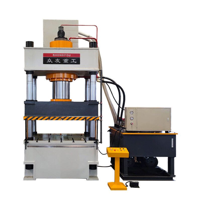
As a professional hydraulic press manufacturer in China, Zhongyou Heavy Industry Machinery Co., Ltd. is committed to providing you with high - quality hydraulic press equipment and professional knowledge related to hydraulic presses. If you have any questions or needs, please contact us!

 EN
EN AR
AR BG
BG HR
HR FR
FR DE
DE EL
EL HI
HI IT
IT JA
JA KO
KO PL
PL PT
PT RO
RO RU
RU ES
ES SV
SV TL
TL IW
IW ID
ID SK
SK SL
SL UK
UK VI
VI HU
HU MT
MT TH
TH TR
TR AF
AF GA
GA IS
IS AZ
AZ KA
KA BN
BN LA
LA MN
MN NE
NE KK
KK UZ
UZ KY
KY

